As a “prosumer” I have liked the Ubiquiti equipment because it’s not too expensive and at the same time provides advanced functionality that I like to tinker with. After switching to an EdgeRouter, I recently swapped one of my two access points with the UniFi nanoHD access point. The EdgeRouter works independently, but the UniFi HD provides a lot more options when controlled using the UniFi Controller. For this, I had a Raspberry Pi 3 lying around so instead of getting the UniFi Cloud Key, I decided to set up the controller on the Raspberry Pi.
I work from home most of the days and generally keep my office door closed to keep distractions to a minimum. I also tend to be on video and audio calls quite a bit. When I am talking on the calls, then it is easy for my family to know not to come in, but when I am listening, then they obviously cannot tell. There have been times when I am on video calls and have had a family member walk in, not knowing. Those can be awkward at times.
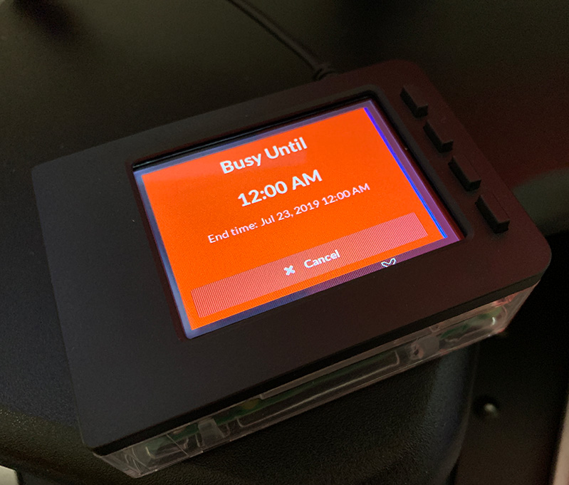
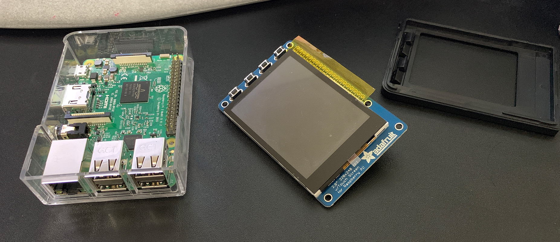
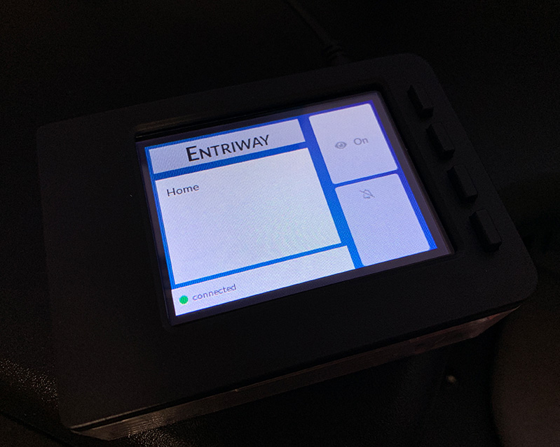
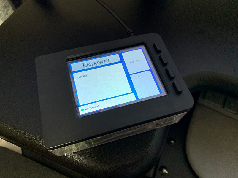
Now, what does this all have to do with the Raspberry Pi? In addition to the Raspberry Pi, I also had a 2.8″ Adafruit PiTFT lying around that I did not end up using in another project. I was planning on having the Raspberry Pi running all day for the UniFi Controller anyway, so why not give it another purpose? So, I decided to create a small digital sign that I could control remotely and put it outside my door for people to know what I was up to. Overkill? Why, yes it is, but it was also fun. Actually, the real overkill would have been this solution running on a rechargeable battery! I called this the “Entriway.”
First Challenge – Deciding the Development Stack
I have been a fan of the go programming language for server-side stuff, but I have always wanted to try out nodejs for server-side programming. Given that this project was for fun, I decided to give nodejs a try. For the UI, initially, I was thinking of writing directly to the framebuffer, but I ended up going with booting into a Chromium instance and launching a React app that presented the UI because I didn’t want to worry about low level UI loops and stuff like drawing rectangles and fonts.
Having a server side backend that controlled the hardware allowed me to develop the React app locally on my computer and still access the GPIO and other hardware functionality. The backend could also monitor the tactile switches and respond whenever needed; e.g., I hooked up the first button to turn the screen on and off.
Since I was doing this project mostly for fun and learning, I decided to use another technology that had been on my list for some time: WebSockets. WebSockets allowed me to not worry about implementing hacks like polling for changes and other things, and had the nice side effect that I could write a single app which I could also access from my desktop or the cellphone browser.
As if that wasn’t enough, I also added React Hooks to the mix as a learning exercise. The project was simple enough that I could have likely survived with simple JavaScript, but where would be the fun in that. So, I ended up with a nodejs backend, React frontend, and using WebSockets for communication. Then began the fun part of bringing it all together.
At one point, I had also thought of using Electron and had it booting, but I gave up on that because the starter code that I had found came with way too many things and the accompanying code compilation on the Raspberry Pi was quite slow.
Second Challenge – Turning Off the Screen using GPIO
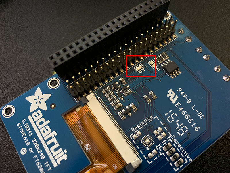
Given my use case, I did not want to keep the PiTFT on all the time and instead wanted to only turn it on when I was busy or when I pressed one of the tactile switches. Unfortunately, the capacitive touchscreen version of PiTFT does not come with the ability to do this out of the box. To accomplish this we have to connect the jumper #18 as instructed by the Adafruit guide. I had an old soldering iron in a box somewhere which took a bit to find, but then I didn’t have any solder wire! Fortunately, I had some old projects that had just enough solder which I ended up salvaging.
Once jumper #18 was connected, I was able to control the backlight using GPIO #18.
gpio -g mode 18 pwm
gpio -g pwm 18 100
gpio -g pwm 18 1000
gpio -g pwm 18 0
Third Challenge – Incorrect Touchscreen Orientation
For some reason, when I first did the PiTFT setup using the Adafruit scripts it had the correct screen and touch input orientation, but after a few restarts that got messed up. Re-running the scripts did not help either. After some troubleshooting, I noticed that the drivers on my specific unit were different than the one that the Adafruit guide had and the device showed up as “generic ft5x06” instead of the ft6x06 or the other one that the scripts and guide show. This required a little adjustment in the udev rules. Here is what /etc/udev/rules.d/90-ft5x06.rules looks like.
SUBSYSTEM=="input", ATTRS{name}=="generic ft5x06*", ENV{DEVNAME}=="*event*", SYMLINK+="input/touchscreen"
After the above change I also needed to install xserver-xorg-input-evdev.
apt-get install xserver-xorg-input-evdev
Then came a change to the newly created /usr/share/X11/xorg.conf.d/10-evdev.conf as shown below.
Section "InputClass"
        Identifier "evdev touchscreen catchall"
        MatchIsTouchscreen "on"
        MatchDevicePath "/dev/input/event*"
        Option "TransformationMatrix" "0 1 0 -1 0 1 0 0 1"
        Driver "evdev"
EndSection
Yes, I know that the udev rule that I showed above creates a symbolic link which doesn’t have much to do with this 10-evdev conf, but I do remember seeing some functionality needing the input/touchscreen link.
After the above steps, I finally had the touch input working correctly. The above solution required reading a lot of forum posts and google searches.
Smooth Sailing
Once I overcame the challenges above, the rest was basically reading about Express, React Hooks, WebSockets, and debugging. I went with express generator for the backend server skeleton and create-react-app for the React app skeleton. I also configured the node server to run using systemd so it would start up on boot.
More to Come
This is not the end. Here are a few things that I will likely work on in the future.
- The UI is very rough and can be cleaned up a bit.
- The nodejs library for controlling GPIO, pigpio, requires root access. I believe it can be configured to run as a non-privileged user, but I haven’t gotten around to that yet.
- Xorg doesn’t take the full screen and I need to figure out how to make it span the full screen.
- Display some basic stats from the UniFi Controller on the home screen.
- Configure one of the buttons to initiate a shutdown.